Engineering education — process control training rig
Digital Twin Training Rig — S7-1500 and Simulink over OPC UA
A pump, level and flow rig whose PLC talks to a Simulink twin over OPC UA, so students tune single-loop and cascade PID in simulation and then run the same controller on real hardware.
- Role
- Simulink and OPC UA integration — plant models, PID and cascade loops, tuning sessions, teaching material
- Company
- Pranakorn Energy (part-time)
- Period
- May 2025 – Jun 2026
- Platforms
- Siemens S7-1500 · TIA Portal V17 · MATLAB / Simulink · OPC UA · Industrial Communication Toolbox
Highlights
- The same Simulink controller runs against the plant model or the real rig — one switch
- Level–flow cascade (level PI → flow PI → control valve) on a pump loop with a VSD
- Material for weeks 9–15 of a process-control course — labs, pre- and post-tests, videos
- The rig later became the plant for the cloud lab every student connects to
Problem
Process-control students meet PID in two places that never touch: on paper, and in a simulator where the plant behaves perfectly. The one real rig in the lab is slow to set up, shared by the whole class, and a bad tuning can overflow a tank.
The course needed a bridge — a model of the rig that behaves like the rig, connected to the rig’s own PLC, so a controller designed in Simulink can be tried safely and then run for real without being rewritten.
My role & scope
I built the Simulink side and the link to the PLC, working with the professor and the PLC programmer on the rig:
- Plant models of the level and flow loops
- PID and cascade controllers in Simulink, and the MATLAB functions that read and write the PLC
- The tag contract with the PLC program: setpoint, process value and output for each loop
- Tuning sessions on the rig, recorded as teaching videos
- Course material for the control-loop weeks
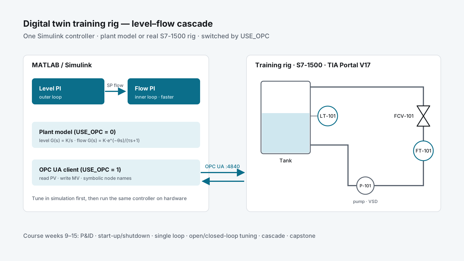
The rig: one pump loop with a level transmitter, a flow transmitter, a control valve and a pump on a variable-speed drive, controlled by an S7-1500 programmed in TIA Portal V17.
Approach
Simulink                                      S7-1500 (OPC UA server, port 4840)
Level PI ──SP_flow──► Flow PI ──MV──┐
   ▲                     ▲          │  USE_OPC = 0 → plant model in Simulink
   │                     │          └► USE_OPC = 1 → write MV, read PV over OPC UA
   └──── PV_level ◄──────┴── PV_flow ◄──────────────── LT-101 · FT-101 · FCV-101
Model the plant before tuning it
The level loop is modelled as an integrating process, G(s) = K/s; the flow loop as first order plus
dead time, G(s) = K·e^(−θs)/(τs + 1). Parameters come from step tests on the rig, so the model’s
gain, time constant and dead time are measured, not guessed. That is what lets a tuning found in
simulation carry over to the hardware.
OPC UA instead of a second PLC program
The S7-1500 has an OPC UA server built in. MATLAB’s Industrial Communication Toolbox connects to it, browses the address space and reads and writes the loop tags by their symbolic names. The rig needs no extra hardware or licence to talk to Simulink, and the same tag names work in every model.
Cascade, then compare
The outer level controller sets the setpoint of the inner flow controller, which drives the control valve. The inner loop is tuned first and made faster than the outer one. Students then run the single-loop and cascade versions against the same disturbance and compare the responses.
One client or a whole class
Two ways to expose the PLC were compared. Serving OPC UA straight from the PLC gives the lowest latency and needs no licence, but every client adds load to the PLC cycle and needs network access to it. An industrial PC as a gateway keeps the PLC isolated and its load constant, at the cost of extra latency and a server licence. Direct access suits a lab bench with one or two clients; more clients call for the gateway or for tight network rules — the second route was taken in the cloud lab.
Delivery
- Simulink models revised through many versions as the PLC program evolved across 2025 and 2026
- Tuning sessions for level and flow on the rig, recorded for students (February 2026)
- Course plan for weeks 9–15: instrumentation and P&ID symbols, PLC architecture and start-up and shutdown sequences, basic loops and trial-and-error tuning, pump curves in open loop, closed-loop tuning, cascade control, and a capstone — each week with a pre-test, a post-test and a video
- A teaching chapter on level–flow cascade control, with the P&ID, faceplates and worked error and controller-output examples
Result
- Students tune in simulation first, then run the same controller on the real rig
- Experiments that used to take a lab session to set up can be repeated from a laptop
- One rig serves a whole class, because most of the work happens on its twin
- The models and the tag contract became the basis of the cloud lab used in 2026
Skills used
Process modelling (integrating and FOPDT processes) · PID and cascade tuning · MATLAB / Simulink · OPC UA (S7-1500 server, MATLAB client) · Siemens TIA Portal V17 · reading P&IDs · teaching control theory with real hardware.